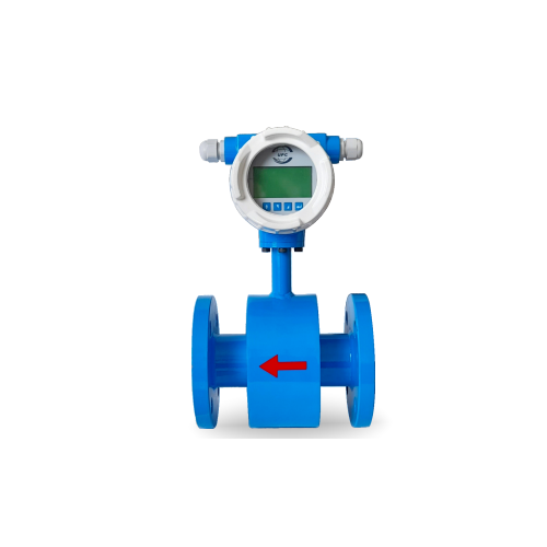
Electromagnetic Flow Meter UPCS-MAG-110
| Product Name | Electromagnetic Flow Meter UPCS-MAG-110 |
|---|---|
| Weight | 1.000000 |
| Brand | UPC |
| COUNTRY OF MANUFACTURE | India |
| HSN Code | 90261010 |
| Freight | To pay by Customer, extra at actuals. Godown Delivery |
| Category | Hydraulics, Hydraulic Accessories, Measuring Equipments, Water Flow Meter |
| Product Code | SBC-0153 |
Electromagnetic Flow Meter UPCS-MAG-110
MAKE: “UPC”
Electromagnetic flow meters are mainly used in various
industries, ETP, STP, WTP Plants, Borewell, Chemical
Petrochemicals, Fertilizer Beverage, Process Industries and
for conductive liquids for measuring the flow rate & totalizer
Working Principle :
Electromagnetic Flow meters are based on
Faraday’s Law of Electromagnetic Induction
In an Electromagnetic Flow meter, the magnetic field is
generated by a set of coils. As the conductive liquid
passes through the magnetic field, an electric
voltage is induced in the liquid which is directly
proportional to its velocity. This induced voltage is
perpendicular to both, the liquid flow direction and the
electromagnetic field direction. the voltage sensed by
the electrodes is further processed by the transmitter to
give standardized output signal or displayed inappropriate engineering unit.
| Sr.no. | Parameters | |
| 1 | Media | Liquids (Conductive) |
| 2 | Nominal dia (mm) | 15 to 3000 |
| 3 | Working pressure | 10, 16, 25, 40 (Kg/cm²) |
| 4 | Working Temperature | 150°C for PTFE Lining & 85°C for Rubber Lining |
| 5 | Electrode material | SS 316L Std.* | HASTALLOY C | PLATINUM | TITANIUM | TENTALUM |
| 6 | Sensor Lining | Std. Rubber*/PTFE |
| 7 | Display Version | Integral/Remote |
| 8 | Measuring Tube material | SS 304 Std.* |
| 9 | Sensor housing material | Std. CS* | SS304 | SS316 optional |
| 10 | End connection | Flange/Wafer/Tri-clamp/SMS |
| 11 | Flange standard | ASA 150# | ANSI 150 | PN10 | PN16 | PN25 | PN40 |
| 12 | Measuring range | 0.2 to 12m/sec. Bidirectional |
| 13 | Accuracy % of measured value | ±0.5% (±0.2% consult Factory) |
| 14 | Conductivity | Liquids (Conductive) |
| 15 | Repeatability | >5 μs/cm |
| 16 | Display | ±0.2% of Span |
| 17 | Display units | GRAPHIC DISPLAY/16X2 LINE DISPLAY |
| 18 | Output | 4-20 mA & RS485 |
| 19 | Power Supply Options | 1. 85-260 V AC 2. 24V DC 3. Battery Operated |
| 20 | Protection Class for Sensor | Std. IP 65 | IP67 | IP68 |
| 21 | Protection Class for Transmitter | IP66 | IP67 | IP68 |
| 22 | Installation | Inline Flanged Type |
Installation Precaution
Installation location should be such that the Flowmeter will always remain full of liquid Minimum 5D inlet & 3D outlet straight lengths should be maintained at installation locations where ‘D’ is
the pipe diameterThe Flowmeter installation location should be free of bends, slbows, tees, valves, etc.
| Returns Policy: |
| 1. | Once orders are placed, cancellations are not permitted. |
| 2. | Payments for orders will not be adjusted or refunded in case of cancellation. |
| Shipping & Delivery Policy: |
| 1. | 100 INR will be charged as shipping fee if buyer and seller are from same city. If Buyer and Seller are from different cities, the shipping charges will be on "To Pay Basis" or at actuals. |
| 2. | Shipping freight costs will be additional and based on actuals, to be borne by the buyer. |
| 3. | Additional shipping services such as courier or door delivery will incur extra charges, to be borne by buyer on extra at actuals basis |
| 4. | Material will be shipped exclusively on a To-Pay basis for Godown Delivery only. |


