Analog Addressable Fire Panels - FPA-1000 | BOSCH

| Product Name | Analog Addressable Fire Panels - FPA-1000 | BOSCH |
|---|---|
| Weight | 1.000000 |
| COUNTRY OF MANUFACTURE | India |
| Brand | Bosch |
| HSN Code | 85319000 |
| System Type | ADDRESSABLE |
| Model | FPA-1000-NE |
| Freight | To pay by Customer, extra at actuals. Godown Delivery |
| Category | Alarm System, Addressable System, Fire Safety |
| Product Code | CPK-0028 |
Analog Addressable Fire Panels - FPA-1000 | BOSCH
• FPA‐1000 Analog Addressable Fire Panels
• Support for up to 508 points on two analog addressable loops
• Built-in Ethernet connector for web-browser based programming and
Conettix Alarm-over-IP communication
• Two on-board NACs and dual-line PSTN DACT
• Peer-to-peer networking of up to eight -V2 panels in a single group
• Suited to a wide range of applications and compatible with the latest Bosch solutions - including 440 Series Multi-criteria detectors
The FPA‐1000 Analog Addressable Fire Panels are a scalable solution for fire detection. Protect your small office with a single system or connect multiple panels together as your needs grow. Networking capabilities support the monitoring of up to 8 interconnected panels (2,000 addressable points) in one system for campuses or other large commercial environments. The FPA‐1000 panels combine complete built-in Fire Alarm Control Panel (FACP) equipment such as Notification Appliance Circuits (NACs), Signaling Line Circuits (SLCs), relays, power supply, Digital Alarm Communicator Transmitter (DACT), and Ethernet connection with expandability using the option bus or plug‐in boards. The two integrated NACs can be expanded with remote addressable NAC power boosters and programmed with specific activation patterns.
The control panel includes one SLC that supports 254 addressable points (254 analog detectors or modules, or 127 analog sounder bases in combination with a suitable detector). The control panel is easily expandable with the FPE‐1000‐SLC Signaling Line Circuit Plug-in Module, doubling the address points to 508.
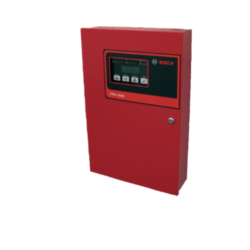
The panel has a compact and solid metal housing with a keyed lock and a removable dead front door to access electronics. It features surface and semi-flush mounting options. On the front of the panel, six light-
emitting diodes (LEDs) show Fire, Carbon Monoxide (Gas) Alarm, Power, Supervisory, Silenced, and Trouble conditions. The built‐in keypad can be used for total system control and programming even when wearing fireman gloves. In addition, a large 4‐line by 20‐character alphanumeric LCD display shows programmed device point information. Four keys enable Drill, Reset, Silence, and Acknowledge functions.
The FPA‐1000 panels enable various programming
approaches:
• Front panel programming
• On-site programming, using a laptop with the
possibility of pre-programming at the office
• Off-site programming, with remote access via
Ethernet (browser-based)
Front panel programming provides an auto‐learn function, allowing the installer to configure the system quickly and easily in default mode. Using a local laptop or remote access communication, the programming is carried out by means of a browser‐based user interface. Therefore, no software installation is required. The panel can receive diagnostics from a Web browser running on an internet‐connected PC.
Functions
Peer-to-peer Communications
The FPA‐1000-V2 panels allow peer-to-peer networking of up to eight panels in a single group supporting a system which can include up to 2000 points.
Networked panels act as a single panel enabling all events to be displayed on all units. All connected panels can easily be programmed and controlled via
any connected panel. Ethernet, fiber optic, or 2-conductor wire inter‐panel
connections can be mixed providing flexibility in system design.
System Management
A set of interactive Web pages gives you an instant means to access and record important system functions. This unique feature enables programming
and diagnostic capabilities while off-site, streamlining installation and reducing the time required for servicing the system. And, you can check status and manage the system from virtually anywhere on the
network.
Communications
The FPA‐1000 panels have a dual phone line PSTN/DACT circuit and an Ethernet connection featuring Conettix IP reporting. The panels communicate in Contact ID, SIA, and Modem IIIa2 The panels provide miscellaneous reporting functions such as dialing control and transmission supervision, priorities of report groups, routing to destinations, manual and auto test reports, and Anti-Replay feature. For the primary and secondary account, the following features are programmable:
• Two different phone or IP numbers
• Different dialing types for PSTN (pulse only,
automatic, or tone only)
• Individual PSTN line supervision (audible and visual
trouble signal in the case of a transmission path failure)
• Selectable options for Report Steering Groups
• Programmable supervision time for each IP reporting Conettix account
• Test report frequency individually programmable for each account (4, 6, 24 hour, 7 and 28 day intervals, standard frequency 24 hour)
Applications
The panels are recommended for a wide range of
commercial and public building applications, including:
• Retail - single building applications
• Education - schools and universities
• Residential - apartment buildings
• Commercial - manufacturing plants, warehouses and office complexes
• Government and Public Service - military bases and installations
• Medical - healthcare facilities
Multi-criteria Detectors
A range of pull stations, modules, accessories and detectors are available to meet the needs of your application. These include the new Automatic Fire
Detector 440 family that incorporates multi-criteria technology for higher sensitivity, faster detection, and fewer false alarms.
Gas detection
Integrated gas detection is an important element of your facility’s fire and life safety strategy. Using FCC-380 Carbon Monoxide detectors combined with an addressable monitor module, you can set your system to alarm for carbon monoxide to meet the NFPA requirements for visual and audible annunciation
for this hazardous gas.
Notification Appliance Circuits (NACs)
Two Class A or Class B NACs provide up to 4 A of 24 V power (non-synchronized: 2.5 A per NAC, synchronized: 2.75 A NAC 1 + NAC 2 in total) to operate horns, strobes, bells, and other notification appliances. Each NAC can be programmed to provide Temporal Code 4, Temporal Code 3, and steady, pulsing, and synchronized protocol output for Wheelock, Gentex, and System Sensor notification appliances.
On-board Relays
Three programmable on-board relays default to global alarm (zone 226), global system trouble (zone 227), and global system supervisory (zone 228). They can be programmed to activate on a variety of conditions including gas alarm.
Option Bus
On the Option Bus, the panels support up to:
• eight FMR-1000-RCMD Remote Command Centers
and FMR-1000-RA Remote Annunciators in any
combination
• eight D7030X Series LED Annunciators with eight LED
zones each
• eight D7030X Series/D7032 combinations
• two Octal Relay Modules or Octal Driver Modules
• four FPP‐RNAC‐8A‐4C Remote Notification Appliance
Circuit Power Supplies
The outputs of the Octal Relay Modules or Octal Driver Modules are fully programmable, and can be activated by system events. These outputs have the same programming options as the local relays. Each output operates independently of the other seven to provide complete flexibility. Communication with the D7035/B or D7048 is supervised.
Power
A transformer working with 120 VAC or 240 VAC is supplied standard with the control panel. Two backup batteries with 7 Ah to 18 Ah each fit inside the fire
panel cabinet. A separate battery box can provide higher capacity. An automated battery calculator sheet is available online to aid in battery selection and submittal paperwork.
The panels provide two auxiliary power supplies (one FWR and one DC) with 0.5 A at 24 V each, with switchable AUX/RST. This auxiliary power can run
expansion boards or other low current auxiliary devices.
For installations requiring battery capacity higher than 40 Ah, a regulated and UL1481 Listed external power supply can be used. The external power supply
connects through the panel's battery terminals and is supervised for AC and battery fault by an input module on the SLC.
The FPP-RNAC-8A-4C Remote NAC Booster adds four additional Notification Appliance Circuits (NFPA 72, Class A or Class B) to the fire panel or serves as a power supply for fire protective signaling systems. This regulated power supply provides up to 8 A of power that is used to recharge batteries and operate continuous and intermittent alarm loads. This 8 A of power can be distributed through the four NAC Power Supply circuits that are part of the FPP-RNAC-8A-4C. The FPP-RNAC-8A-4C is UL Listed for use in
commercial fire alarm applications.
Signaling Line Circuits (SLCs)
The panels communicate with each of the analog addressable devices located on the SLCs. The SLCs allow the use of standard non‐twisted, non‐shielded
wiring. Each panel supports two Class B circuits or one Class X circuit or one Class A circuit per SLC.
Certifications and approvals
| Region | Regulatory compliance/quality marks | |
| USA | UL | FSZI.S1871: Emergency Alarm System Control Units (ANSI/UL 2017); UOJZ: Control Units, System (ANSI/UL 864) |
| FM | FPA-1000 | |
| CSFM | see the Bosch website (www.boschse- curity.com) |
|
| FDNY- CoA |
6101 |
Installation/configuration notes
Mounting Considerations
The cabinet can be either semi-flush (requires optional FPM‐1000‐SFMK Semi-flush Mounting Kit) or surface mounted.Depending on the configuration and the battery selection, the FPA‐1000 can be heavy. When attaching the enclosure to a surface, use mounting hardware (not supplied) capable of supporting this weight, and reinforce the wall as necessary.
Wiring Considerations
The length of wire allowed between the control panel and the last device on a wiring run depends on the current drawn on that wiring run. Reducing the
number of devices on a wiring run allows the individual runs to be longer.
If not otherwise specified, use wire gauge 12 AWG to 18 AWG (ISO 4 mm2 to 0.75 mm2).
Notice
Shared cable is not recommended for the Option Bus, addressable‐points bus, telephone, or NAC wiring. Do not run wiring for NAC, Option Bus, and SLC in the same conduit. Avoid shielded or twisted-pair wire except for network connections and special applications where a reduced length of wiring (roughly 50%) is acceptable for tolerating a harsh electrical environment.
Point Capacity/Configuration
Each FPA-1000-V2 panel supports up to 508 addresses, 254 per loop. All compatible detectors and modules are addressed using the D5070 Programmer.You can use addresses 1 to 127 for any combination of detectors and modules. SLC devices that support the newest DCP protocol version 2.0 can use addresses 1 to 254. For a listing of devices that can use addresses
up to 254, see the SLC Address Assignment section of the FPA-1000 Installation and Operation Guide.Detectors connected to a sounder base can use only addresses 1 to 127. The sounder bases are addressed automatically by the panel, depending on the detector’s address (detector address +127).
Technical specifications
| Electrical | |
| Mains power supply (primary) | |
| • Supervision |
Supervised for the presence of AC power |
| • Voltage |
120 VAC, 60 Hz, 1.1 A maximum, or |
| Power supply (secondary) with battery backup | |
| • Voltage | 24 VDC |
| • Supervision |
Supervised for the presence of AC power |
| • Current consumption (standby) |
1.25 A maximum |
| • Current consumption (alarm) |
5 A maximum 1.0 A maximum shared between panel and SLC(s) • Panel ≤ 250 mA • SLC 1 = 60 mA/card + 220 mA/loop maximum • SLC 2 = 60 mA/card + 220 mA/loop maximum 4.0 A maximum shared between NACs, Option Bus, and AUX power • NACs (non-synchronized) • NAC 1 =2.5 A maximum • NAC 2 = 2.5 A maximum • NACs (synchronized) • NAC 1 + NAC 2 in total = 2.75 A maximum • Option Bus = 0.5 A maximum • AUX/FWR = 0.5 A maximum • AUX/RST = = 0.5 A maximum |
| • Battery capacity | 7.0 Ah minimum, 40 Ah maximum |
| • Charge current | 2.0 A maximum |
| • Fuse | 15 A blade-type |
| • Suitable battery type | Two 12 VDC in series (7 Ah or 18 Ah in enclosure, 24 Ah or 38 Ah in additional battery box) Recommended Manufacturers: POWER SONIC: PS-1270, PS-12170, PS‐12180 YUASA: NP7-12, NPG18-12 |
| • Maintenance |
Replace batteries when they fail the Battery Load test |
| AUX/FWR Full Wave Rectified |
500 mA at 24 V FWR (17 to 31 VRMS), non‐switched, power- |
| AUX/RST Resettable |
500 mA at 24 V FWR (17 to 31 VDC), switched, power- |
| Line impedance for ground fault detection (Option Bus, SLC, NAC, secondary power circuit, City Tie/ Local Energy, AUX) |
15 kΩ |
| Option Bus (OB) | |
| Voltage |
Nominal 12 VDC, power-limited, supervised |
| Current | 500 mA maximum |
| Configuration | 1 Class B |
| Circuit wiring distance | 4000 ft. (1219 m) maximum, depending on wire gage and connected devices |
| Notification appliance circuits (NACs) | |
| Mainboard NACs | Two (NAC 1 and NAC 2) |
| NAC power from panel |
Nominal 24 V FWR (17 to 31 VRMS), regulated, power- 2.5 A per NAC, maximum current |
| Line impedance | 1.45 Ω maximum |
| Configuration | Two Class B or two Class A |
| Signaling line circuits (SLCs) | |
| Voltage | Nominal 39 VDC (29 VDC to 40 VDC), power‐limited, supervised |
| Current | 204 mA (per FPE-1000-SLC) |
| Circuit resistance | <50 Ω |
| Circuit capacitance | <1 ΩF |
| Circuit inductance | <1 mH |
| Configuration |
1 or 2 Class B or 1 Class A or 1 Class X |
| City Tie | |
| Circuit resistance | 65 Ω maximum |
| Wire gauge |
12 AWG to 18 AWG (ISO 4 mm2 to 0.75 mm2) |
| Type of connection | In series |
| Alarm, trip coil | 24 VDC |
| Alarm current | 250 mA DC (momentary) |
| Supervisory/standby current | <50 mA DC |
| Trip coil resistance | 14.5 Ω |
| Nominal coil voltage | 3.65 VDC, power-limited, supervised |
| City Tie - Reverse Polarity Module | |
| Nominal voltage | Nominal 24 VDC (26.4 VDC maximum), power‐limited, supervised |
| Output current | 33 mA maximum |
| Supervisory/standby current | 5 mA |
| Networking cards | |
| Current (per card) | FPE-1000-NE: 100 mA FPE-1000-NF: 170 mA FPE-1000-NW: 330 mA |
| Circuit wiring distance (actual length depends on connector quality) |
FPE-1000-NE: 328 ft. (100 m) FPE-1000-NF: 6560 ft. (2000 m) or 10 db loss FPE-1000-NW: 3280 ft. (1000 m) maximum |
| Returns Policy: |
| 1. | Once orders are placed, cancellations are not permitted. |
| 2. | Payments for orders will not be adjusted or refunded in case of cancellation. |
| Shipping & Delivery Policy: |
| 1. | 100 INR will be charged as shipping fee if buyer and seller are from same city. If Buyer and Seller are from different cities, the shipping charges will be on "To Pay Basis" or at actuals. |
| 2. | Shipping freight costs will be additional and based on actuals, to be borne by the buyer. |
| 3. | Additional shipping services such as courier or door delivery will incur extra charges, to be borne by buyer on extra at actuals basis |
| 4. | Material will be shipped exclusively on a To-Pay basis for Godown Delivery only. |