Addressable Switch Interface Modules with Dual Isolators | XTRI-R | Siemens
| Product Name | Addressable Switch Interface Modules with Dual Isolators | XTRI-R | Siemens |
|---|---|
| Weight | 1.000000 |
| COUNTRY OF MANUFACTURE | India |
| Brand | Siemens |
| HSN Code | 8537109000 |
| System Type | ADDRESSABLE |
| Model | XTRI-R |
| Freight | To pay by Customer, extra at actuals. Godown Delivery |
| Category | Alarm System, Fire Safety, Control Module |
| Product Code | CPK-0091 |
Addressable Switch Interface Modules with Dual Isolators | XTRI-R | Siemens
INTRODUCTION
The XTRI Series Addressable Modules from Siemens Industry, Inc., shown in Figure 1, interface direct shorting devices to the device loop circuit of the Desigo FC2025/FC2050/FV2025/FV2050 and Cerberus PRO FC922/FC924 /FV922/FV924 Fire Alarm Systems. Refer to the Configuration Tool,Document IDA6V10315023.
The XTRI modules support two operation modes: polarity insensitive mode and isolator mode. The module can be wired for either mode (refer to Figures 8 through 13). During the isolator mode, the built-in dual isolators will work at both sides of the module to isolate the line short in front or behind the module.
The XTRI modules are available in three models. The XTRI-S, P/N S54370-B3-A1, and XTRI-R, P/N S54370-B1-A1, can monitor a normally open or closed dry contact. The XTRI-S can only monitor and report the status of the contact, while the XTRI-R incorporates an addressable Form C relay. The XTRI-D, P/N S54370-B2-A1, is a dual input module that supervises and monitors two sets of dry
contacts.
PROGRAMMING INSTRUCTIONS
Refer to Figure 2 to locate the opening on the XTRI cover that allows access to the programming holes which are on the XTRI printed circuit board.To connect the XTRI to the DPU Programmer/Tester, insert the plug from the DPU cable provided withthe Programmer/Tester into the opening on the front of the XTRI shown in Figure 2. The plug has no polarity and can be inserted into the holes at either direction.
CAUTION: To prevent potential damage to the DPU, DO NOT connect an XTRI to the DPU until all connectors of the same polarity are removed from the device line of the XTRI.Follow the instructions in the DPU Manual (P/N 315-033260) to program the XTRI to the desired address. Record the device address on the address label, which comes with the product, and place it
on the module or on the XTRI front panel. The XTRI can now be installed and wired to the system.
CAUTION: Deactivate P2 circuit by either or both of the following: Using the PMI, bypass the circuit being modified, and/or physically disconnect the circuit from the P2 source.
NOTES:
1. There can be any number of normally closed or normally open switches.
2. The end of line resistor must be located at the last switch.
3. Do not wire a normally closed switch across the end of line resistor.
4. Only for use with status applications.
Wiring Switches
NOTES:
1. Mount EOL on the TB-EOL terminal.
2. The EOL resistor must be mounted at the last switch (normally open switch).
3. TB-EOL will not come with the package of product. Use Siemens TB-EOL, P/N S54322-F4-A2, or equivalent.
4. EOL 470 ohms, 1% 1/2W will come with the package of product.
5. For multi-normally closed switches monitoring, the open fault between switch will not be supervised.
XTRI-R CONTROL MODULE
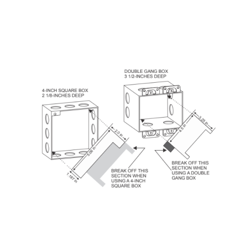
The XTRI-R Control Module Barrier must be used when the XTRI-R relay contacts are connected to non-power limited lines. Break apart the barrier to the correct size and shape shown in Figure 6 for either the 4-inch square or double gang box. Install the barrier diagonally into the backbox to create two separate compartments within the backbox to separate the wires, as shown in Figure 6.
| Returns Policy: |
| 1. | Once orders are placed, cancellations are not permitted. |
| 2. | Payments for orders will not be adjusted or refunded in case of cancellation. |
| Shipping & Delivery Policy: |
| 1. | 100 INR will be charged as shipping fee if buyer and seller are from same city. If Buyer and Seller are from different cities, the shipping charges will be on "To Pay Basis" or at actuals. |
| 2. | Shipping freight costs will be additional and based on actuals, to be borne by the buyer. |
| 3. | Additional shipping services such as courier or door delivery will incur extra charges, to be borne by buyer on extra at actuals basis |
| 4. | Material will be shipped exclusively on a To-Pay basis for Godown Delivery only. |


