65mm DI Hydraulic Check Control Valve PN 16 Flanged LIV-ACV-HCV-DI-FE-003 Lehry

| Product Name | 65mm DI Hydraulic Check Control Valve PN 16 Flanged LIV-ACV-HCV-DI-FE-003 Lehry |
|---|---|
| Weight | 1.000000 |
| DISC | DI |
| Brand | LEHRY |
| Test Certificate | No |
| COUNTRY OF MANUFACTURE | India |
| Model | LIV-ACV-HCV-DI-FE-003 |
| Valve Type | Flanged Ends |
| Valve Body | Ductile Iron (ASTM A536) |
| IBR Approved | No |
| HSN Code | 84818030 |
| Valve Size | 65mm |
| Freight | To pay by Customer, extra at actuals. Godown Delivery |
| Category | Hydraulics, Hydraulic valves, Check Valve, Check Control Valve |
| Product Code | LIV-0005-65mm |
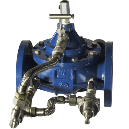
65mm DI Hydraulic Check Control Valve PN 16 Flanged LIV-ACV-HCV-DI-FE-003 Lehry
Lehry ACV Hydraulic Check Valve, Globe Type, Flanged End as per PN.16.
Technical Details :-
- Body : Ductile Iron (ASTM A536)
- Stem : Stainless Steel
- Seat : Brass
- Spring : SS.304
- Disc Retainer : Brass
- Pressure : PN 16
- Pilot : SS
- Valve Type :- Flanged End
LEHRY Hydraulic Check Control valve Is Used To Reduce A Higher Fluctuation Upstream
Pressure, To A Constant Desired Downstream Pressure, Through An Adjustable Pilot System.
The Downstream Pressure Is Maintained A Constant, Regardless Of Changes In Upstream
Pressure And Flow.
The Valve Controls The Opening And Closing Speed Through The Two-Way Pipe And The
Regulator Valve, When The Downstream Pressure Is Higher Than The Upstream Pressure, The
Valve Closes. When The Downstream Pressure Is Below The Upstream Pressure, The Valve
Opens. The valve Adjusts The Opening And Closing Speed Automatically By Two Way
Controlling, Reducing Turbulence, And Water Hammer.
Materials of Valves
| P No | Name | Cast Iron, Ductile Iron |
| A | Body | Brass |
| B | Ball | Brass |
| B1 | Ball | Brass |
| C | Exhaust Valve | Brass |
| D | Ball | Brass |
| G | Filter | Brass |
| H | Reducing Orifice | Stainless Steel |
| I | Throttle Valve | Brass, Stainless Steel |
| M | Priority Valve | Stainless Steel |
| Vertical Installation SpringAssembly (Optional)B | Stainless Steel | |
| Working Pressure | PN16 |
Description & Materials
| Technical Specification | Part Name | Material | Part Name |
| Design Standard : BS EN 1567 Face to Face :EN558-1 | Body | DI | Diaphragm |
| Spring | SS | O-Ring | |
| Flange Drilling : EN1092-2 / ANSI | Seat | NBR | Guide Bush |
| Stem | Bronze | Coating |
Basic Information of Main Valve
| Medium | Standards | Connection |
| Medium: Water, Oil & Gas | Design Standards BSEN 1567 | Face to Face EN 558-1 |
| Pressure Range: PN16, ANSI CL150 | Test Standard EN 1226-1 | Flange Drilling EN 1092-2 ANSI / 150 |
Working Principle
When Downstream Pressure Is Lower Than Setting Pressure, Pilot M Opens Automatically, The Pressure Contained In The By-Pass
Circuit Doesn’t Apply Any Force On The Membrane Of Main Valve A. Thus The Closing System Is Released And Lifted. The Valve Throttles
To Open Position To Increase Downstream pressure To The Desired Level.
When Downstream Pressure Is Higher Than Setting Pressure, Pilot M Is Closed Automatically, The Pressure Contained In The
Membrane Of Main Valve A. Thus The Closing System Drop Down And The Valve Throttles To Closed Position To Reduce Downstream
Pressure To The Desired Level.
- Control And Maintain A Preset Pressure
- This Valve Prevent Over Pumping Of A Pump If The System Demand Exceeds The Pumping Capacity
The Upper Reaches Of The Pressure Range: 0.00-2.76 Bar, 1.72 – 8.62 bar, 6.89 – 17.23 Bar, 17.23 – 27.23 bar
Pressure Reducing Valve
Cavitation Guide Chart
After Selecting The Valve Size, Locate Inlet And Outlet Pressure On This Chart. If The Intersection Point Falls In The Shade
Area, Cavitation Can Occur. Operation Of Valve Continually In The Cavitation Zone Should Be Avoided
Anti-Cavitation Solution
The Anti-Cavitation Mold Is Designed For Application Where There Is A High Potential For Damage From Cavitation, Which
Provides Optimum Internal Pressure Control Through A Unique Anti-Cavitation Trim Design.
Relieving The Damage Of Cavitation With Multi-Stage Pressure Reducing
Note
- Connection PN16-PN25 Flange Drilling To Be Indicated When Ordering. Threaded Connection On Request ANSI – ASI Drilling On Request.
- Contact Us For The Vertical Installation Of Control Valves Above DN200. & DN 350 An Above.
Installations
- Flush the pipeline before inserting the valve
- Install The Valve WIth The “Arrow” On Body Pointing Towards The Reduced Pressure Area (or with The Flange Tagged “INLET)
Toward The High Pressure Are.) - Attached Subassemblies To Main Valve If Necessary.
- Allow Enough Clearance Above Valve For Removal Of Piston Assembly
Start - Up
- Install Pressure Gauges For Inlet And Outlet
- Open Both Shut-Off Valves On The Control Assembly
- Open Air Bleeder At The Top Of The Valve. (Reclose After Step 4 Or Step 5)
- Open Main Line Shut-Off valve (Usually A Gate Or Butterfly valve) On The Outlet Side Of The Main Valve About ¼ Open
- Slowly Open Main Line Shut-Off Valve On The Inlet Side And Observe Pressure Gauges
- When The Outlet Pressure Gauge Shows That The Downstream Pressure Is Being Controlled, This Shut-Off valve may be
Opened More Rapidly. - If The Outlet Pressure Requires Adjustment, Turn The Adjusting Screw Of The Pilot Valve Counter Clock – Wise To Decrease,
Clockwise To Increase. Caution: Any Adjustments Should Be Done Slowly.
50mm Lehry DI Hydrulic check valve F/E - PN 16
| Returns Policy: |
| 1. | Once orders are placed, cancellations are not permitted. |
| 2. | Payments for orders will not be adjusted or refunded in case of cancellation. |
| Shipping & Delivery Policy: |
| 1. | 100 INR will be charged as shipping fee if buyer and seller are from same city. If Buyer and Seller are from different cities, the shipping charges will be on "To Pay Basis" or at actuals. |
| 2. | Shipping freight costs will be additional and based on actuals, to be borne by the buyer. |
| 3. | Additional shipping services such as courier or door delivery will incur extra charges, to be borne by buyer on extra at actuals basis |
| 4. | Material will be shipped exclusively on a To-Pay basis for Godown Delivery only. |