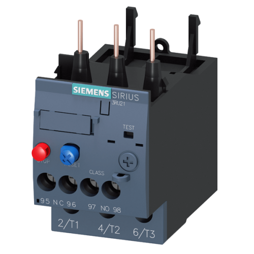
3RU2126-1CB00-8K Thermal Overload Relay 1.8...2.5 Siemens Size S0, Class 10 Contactor Mounting

₹1,320.75 ₹1,558.49
In stock
| Product Name | 3RU2126-1CB00-8K Thermal Overload Relay 1.8...2.5 Siemens Size S0, Class 10 Contactor Mounting |
|---|---|
| Weight | 0.180000 |
| Brand | Siemens |
| Test Certificate | No |
| COUNTRY OF MANUFACTURE | India |
| Sizes | S0 |
| Model | 3RU2126-1CB00-8K |
| HSN Code | 85364900 |
| Freight | To pay by Customer, extra at actuals. Godown Delivery |
| Category | Electrical, Relays & Contactor, Thermal Overload Relay |
| Product Code | TNB-0594 |
In Stock ( 200 Units )
3RU2126-1CB00-8K Thermal Overload Relay 1.8...2.5 Siemens Size S0, Class 10 Contactor Mounting
Description
Overload Relay 1.8...2.5 A Thermal For Motor Protection Size S0, Class 10 Contactor Mounting Main Circuit: Screw Auxiliary Circuit: Screw Manual-Automatic-Reset
| Product Brand Name | Sirius |
| Product Designation | Thermal Overload Relay |
| Product Type Designation | 3RU2 |
| Model No | 3RU2126-1CB0 |
| General Technical Data | |
| Size Of Overload Relay | S0 |
| Size Of Contactor Can Be Combined Company-Specific | S0 |
| Power Loss [W] For Rated Value Of The Current At AC In Hot Operating State | 5.7 W |
| Per Pole | 1.9 W |
| Insulation Voltage With Degree Of Pollution 3 At AC Rated Value | 690 V |
| Surge Voltage Resistance Rated Value | 6 kV |
| Maximum Permissible Voltage For Protective Separation | |
| In Networks With Ungrounded Star Point Between Auxiliary And Auxiliary Circuit | 440 V |
| In Networks With Grounded Star Point Between Auxiliary And Auxiliary Circuit | 440 V |
| In Networks With Ungrounded Star Point Between Main And Auxiliary Circuit | 440 V |
| In Networks With Grounded Star Point Between Main And Auxiliary Circuit | 440 V |
| Shock Resistance According To IEC 60068-2-27 | 8g / 11 ms |
| Reference Code According To IEC 81346-2 | F |
| Substance Prohibitance (Date) | 10/01/2009 |
| SVHC Substance Name | Lead - 7439-92-1 |
| Weight | 0.18 kg |
| Ambient Conditions | |
| Installation Altitude At Height Above Sea Level Maximum | 2 000 m |
| Ambient Temperature | |
| During Operation | -40 ... +70 °C |
| During Storage | -55 ... +80 °C |
| During Transport | -55 ... +80 °C |
| Temperature Compensation | -40 ... +60 °C |
| Relative Humidity During Operation | 10 ... 95 % |
| Environmental Footprint | |
| Global Warming Potential [CO2 Eq] Total | 56.6 kg |
| Global Warming Potential [CO2 Eq] During Manufacturing | 1.21 kg |
| Global Warming Potential [CO2 Eq] During Sales | 0.047 kg |
| Global Warming Potential [CO2 Eq] During Operation | 55.4 kg |
| Global Warming Potential [CO2 Eq] After End Of Life | -0.027 kg |
| Main Circuit | |
| Number Of Poles For Main Current Circuit | 3 |
| Adjustable Current Response Value Current Of The Current | 1.8 ... 2.5 A |
| Dependent Overload Release | |
| Operating Voltage | |
| Rated Value | 690 V |
| at AC-3e Rated Value Maximum | 690 V |
| Operating Frequency Rated Value | 50 ... 60 Hz |
| Operational Current Rated Value | 2.5 A |
| Operational Current at AC-3e at 400 V Rated Value | 2.5 A |
| Operating Power | |
| at AC-3 | |
| at 400 V Rated Value | 0.75 kW |
| at 500 V Rated Value | 1.1 kW |
| at 690 V Rated Value | 1.5 kW |
| at AC-3e | |
| at 400 V Rated Value | 0.75 kW |
| at 500 V Rated Value | 1.1 kW |
| at 690 V Rated Value | 1.5 kW |
| Auxiliary Circuit | |
| Design Of The Auxiliary Switch | Integrated |
| Number Of NC Contacts For Auxiliary Contacts | 1 |
| Note | For Contactor Disconnection |
| Number Of NO Contacts For Auxiliary Contacts | 1 |
| Note | For Message "Tripped" |
| Number Of CO Contacts For Auxiliary Contacts | 0 |
| Operational Current Of Auxiliary Contacts At AC-15 | |
| at 24 V | 3 A |
| at 110 V | 3 A |
| at 120 V | 3 A |
| at 125 V | 3 A |
| at 230 V | 2 A |
| at 400 V | 1 A |
| at 690 V | 0.75 A |
| Operational Current Of Auxiliary Contacts At DC-13 | |
| at 24 V | 2 A |
| at 60 V | 0.3 A |
| at 110 V | 0.22 A |
| at 125 V | 0.22 A |
| at 220 V | 0.11 A |
| Contact Rating Of Auxiliary Contacts According To UL | B600 / R300 |
| Protective And Monitoring Functions | |
| Trip Class | Class 10 |
| Design Of The Overload Release | Thermal |
| UL/CSA Ratings | |
| Full-Load Current (FLA) For 3-Phase AC Motor | |
| at 480 V Rated Value | 2.5 A |
| at 600 V Rated Value | 2.5 A |
| Short-Circuit Protection | |
| Design Of The Fuse Link | |
| For Short-Circuit Protection Of The Auxiliary Switch Required | Fuse gG: 6 A, Quick: 10 A |
| Installation/ Mounting/ Dimensions | |
| Fastening Method | Contactor Mounting |
| Height | 85 mm |
| Width | 45 mm |
| Depth | 85 mm |
| Connections/ Terminals | |
| Product Component Removable Terminal For Auxiliary And Control Circuit | No |
| Type Of Electrical Connection | |
| For Main Current Circuit | Screw-Type Terminals |
| For Auxiliary And Control Circuit | Screw-Type Terminals |
| Arrangement Of Electrical Connectors For Main Current Circuit | Top And Bottom |
| Type Of Connectable Conductor Cross-Sections | |
| For Main Contacts | |
| Solid Or Stranded | 2x (1 ... 2.5 mm²), 2x (2.5 ... 10 mm²) |
| Finely Stranded With Core End Processing | 2x (1 ... 2.5 mm²), 2x (2.5 ... 6 mm²), 1x 10 mm² |
| For AWG Cables For Main Contacts | 2x (16 ... 12), 2x (14 ... 8) |
| Type Of Connectable Conductor Cross-Sections | |
| For Auxiliary Contacts | |
| Solid Or Stranded | 2x (0.5 ... 1.5 mm²), 2x (0.75 ... 2.5 mm²) |
| Finely Stranded With Core End Processing | 2x (0.5 ... 1.5 mm²), 2x (0.75 ... 2.5 mm²) |
| For AWG Cables For Auxiliary Contacts | 2x (20 ... 16), 2x (18 ... 14) |
| Tightening Torque | |
| For Main Contacts With Screw-Type Terminals | 2 ... 2.5 N·m |
| For Auxiliary Contacts With Screw-Type Terminals | 0.8 ... 1.2 N·m |
| Design Of Screwdriver Shaft | Diameter 5 ... 6 mm |
| Size Of The Screwdriver Tip | Pozidriv PZ 2 |
| Design Of The Thread Of The Connection Screw | |
| For Main Contacts | M4 |
| Of The Auxiliary And Control Contacts | M3 |
| Safety Related Data | |
| Failure Rate [FIT] With Low Demand Rate According To SN 31920 | 50 FIT |
| MTTF With High Demand Rate | 2 280 a |
| IEC 61508 | |
| T1 Value | |
| For Proof Test Interval Or Service Life According To IEC 61508 | 20 a |
| Electrical Safety | |
| Protection Class IP On The Front According To IEC 60529 | IP20 |
| Touch Protection On The Front According To IEC 60529 | Finger-Safe, For Vertical Contact From The Front |
| Display | |
| Display Version For Switching Status | Slide Switch |
| Returns Policy: |
| 1. | Once orders are placed, cancellations are not permitted. |
| 2. | Payments for orders will not be adjusted or refunded in case of cancellation. |
| Shipping & Delivery Policy: |
| 1. | 100 INR will be charged as shipping fee if buyer and seller are from same city. If Buyer and Seller are from different cities, the shipping charges will be on "To Pay Basis" or at actuals. |
| 2. | Shipping freight costs will be additional and based on actuals, to be borne by the buyer. |
| 3. | Additional shipping services such as courier or door delivery will incur extra charges, to be borne by buyer on extra at actuals basis |
| 4. | Material will be shipped exclusively on a To-Pay basis for Godown Delivery only. |
Write Your Own Review