Smoke Detector (Addressable Multi - Criteria Fire Detector) HFP - 11 - Siemens

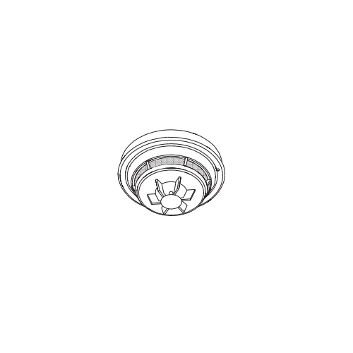
| Product Name | Smoke Detector (Addressable Multi - Criteria Fire Detector) HFP - 11 - Siemens |
|---|---|
| Weight | 1.000000 |
| COUNTRY OF MANUFACTURE | India |
| Brand | Siemens |
| HSN Code | 8531 |
| System Type | CONVENTIONAL |
| Model | HFP-11 |
| Freight | To pay by Customer, extra at actuals. Godown Delivery |
| Category | Alarm System, Fire Safety, Detectors, Smoke Detector |
| Product Code | CPK-0165 |
These instructions are written in accordance with the installation guidelines of NFPA 72, National Fire Alarm Code, and CAN/ULC-S524, The Installation of Fire Alarm Systems.
Fire Print Detectors And Nuisance Alarms
The neural network within each Model HFP-11 FirePrint detector is optimized to reject the most common nuisance alarms for its selected FirePrint Application; e.g. Parking Garage or Health Care. If the detector is exposed to an excess level of smoke or aerosol for an extended period of time, the detector is programmed to make the “safe decision” and signal an alarm condition. Because the amplitude and duration of deceptive phenomena are unbounded, the rule of thumb is to keep detectors as far as practical from sources that can produce an unusually large quantity of smoke for about a minute. This effort during placement of detectors within a FirePrint Application enhances the ability of FirePrint’s
deceptive phenomena rejection. Avoid close proximity of detectors to smoke sources such as oil burners, electric heaters, kitchens, garages, and areas of high relative humidity where condensation may occur.
Air Currents
Before a detector can sense a fire, the products of combustion or smoke must travel from the fire to the detector. This travel is especially influenced by air currents; therefore, consider air movement when designing the system. While combustion products tend to rise, drafts from hallways, air diffusers, fans, etc., may help or hinder the travel of combustion products to the detector. When positioning a detector at a particular location, give consideration to windows and doors, both open and closed, to ventilating systems, both in and out of operation, and to other factors influencing air movement. Do not install a detector in the air stream of a room air supply diffuser. It is better to position a detector closer to an air return.
The distance that products of combustion or smoke travel from a fire to the detector is not usually the shortest linear route. Combustion products or smoke usually rise to the ceiling, then spread out. Average ceiling heights of 8 to 10 feet do not abnormally affect detector response. High ceilings, located in churches, warehouses, auditoriums, etc., do affect detector response and should be considered.
Special Ceiling Construction Factors
Ceiling obstructions change the natural movement of air and combustion products. Depending on the direction of smoke travel, joists and beams can slow the movement of heated air and smoke, while pockets between them can contain a reduced level of smoke. Take obstructions created by girders, joists, beams, air conditioning ducts, or architectural design into consideration when determining area protection. Refer to the Initiating Devices chapter of NFPA Standard 72 for Location and Spacing requirements for specific types of construction; e.g. beam, suspended, level, sloped and peaked ceilings.
HFP-11 DETECTOR PLACEMENT
Although no specific spacings are set for the detectors used for a clean air application, use 30 foot center spacing (900 sqft) from NFPA Standard 72 and CAN/ULC-S524, if practical, as
a guide or starting point for a detector installation layout. This spacing, however, is based on ideal conditions–smooth ceiling, no air movement, and no physical obstructions. In some
applications, therefore, considerably less area is protected adequately by each smoke detector. This is why it is mandatory to closely follow the installation drawings. In all installations
place the detector on the ceiling, a minimum of 6 inches from a side wall, or on a wall, 4 to 6 inches from the ceiling.
If you have any questions regarding detector placement, follow the drawings provided or approved by Siemens Industry, Inc., or by its authorized distributors. This is extremely important! The detector placements shown on these drawings were chosen after a careful evaluation of the area that is protected. Such factors as air currents, temperature, humidity, pressure, and the nature of the fire load were carefully considered. Especially noted were the room or area configuration and the type of ceiling (sloped or flat, smooth or beamed). Siemens Industry, Inc.’s extensive experience in the design of the system assures the best detector placement by following these drawings. Sound engineering judgment by qualified personnel must be followed.
HFPT-11 DETECTOR PLACEMENT
Locate Model HFPT-11 on the ceiling, at least 4 inches from the side walls. For an ideal, smooth ceiling condition, place the detectors at a maximum center spacing of 50 feet (2500 square feet). Locate detectors 25 feet from side walls or room partitions. For FM Approved installations this device has an RTI rating of FAST. Use maximum center spacing of 25 feet (625 square feet). Locate detectors 12.5 feet from side walls or room partitions.
Actual job conditions and sound engineering judgment must determine detector spacing. Consider environmental factors including ambient temperature fluctuation, and the nature of the fire hazard. Room or area configuration and ceiling type (sloped or flat, smooth or beamed) also dictates placement.
Should questions arise regarding detector placement, follow the drawings provided and/or approved by Siemens Industry, Inc., or by its authorized distributors. This is extremely important! The detector placements shown on these drawings were chosen after a careful evaluation of the area being protected. Siemens Industry, Inc.’s extensive experience in design of the system assures the best detector placement by following these drawings.
Temperature – Humidity – Pressure – Air Velocity
The operating temperature range for the HFP-11 and HFPT-11 detectors is 32°F (0°C) to 100°F (38°C). The thermal alarm temperature is rate compensated at 135°F (57°C).Use these
detectors in environments where the humidity does not exceed 93% (non-condensing). Normal changes of atmospheric pressure do not affect detector sensitivity. For HFP-11 open area 0-1200 ft/min applications, use the appropriate application from the FirePrint ASD application list. Use the ASD duct application for 300-4000 ft/min applications a) in above-ceiling and under-floor plenums, b) inside an air duct, and c) in an air duct housing using sampling tubes. Follow detector spacing and location requirements in NFPA 72 Chapter 5 for High Air Movement Areas and Control of Smoke Spread.
When installing Model HFP-11 in existing installations with an existing duct detector housing, order an AD-11UK Air Duct Upgrade Kit DA-304, P/N 500-695967 and use it in that installation. This kit includes the required housing cover, P/N 305-095676. Do not use Model HFP-11 with any other air duct cover
For air duct and open area applications, the HFP-11 smoke sensitivity range is indicated on its nameplate. For application/sensitivity settings, refer to the FireFinder-XLS System Manual, P/N 315-033744, or the FS-250 Manual, P/N 315-049353.
OPERATION
LED Indicators
The Model HFP-11 / HFPT-11 contains an LED indicator capable of flashing either one of three distinct colors: green, yellow, or red. During each flash interval, the microprocessorbased detector checks the following:
• For smoke in its sensing chamber.
• That its smoke sensitivity is within the range indicated on the nameplate label.
• That its critical smoke sensing electronics are operating.
Based on the results of these checks, the LED indicator flashes the following:
| Flash Color | Condition | Flash Interval (Seconds) |
| HFP-11 | ||
| Green* | Normal supervisory operation. Smoke sensitivity is within rated limits. | 4 |
| Yellow | Detector requires service (cleaning or repair) or is operating beyond its environmental specifications. |
4 |
| Red | Alarm | 4 |
| No Flashes | Detector is not powered, or requires repair | - |
| *LED can be turned off by selecting "LED Deactivated" in the Zeus tool or the FS-CT2 tool. | ||
DETECTOR PROGRAMMING
Each detector on a loop must be programmed to respond to a unique system address between 001-252.
• To program the detector address, use the Model DPU Device Programming Unit. Refer to the DPU Manual, P/N 315-033260.
• Record the loop and device number (system address) for the detector on the detector label and on the base to prevent installing the detector in the wrong base. The optional DPU label printer can be used for this purpose.
Detector Guard Programming
When using the DGH-11 or the STI 8100IS detector guards with with the FireFinder-XLS system, program the HFP-11 for DUCT Application using the Zeus Programming Tool. For FS250 systems, program the HFP-11 for DUCT Application using the FS-CT2 Configuration Tool.
System Configuration
Model HFP-11 can be programmed to optimize environmental response using Application Specific Detection (ASD). All parameters, such as Sensitivity, Pre-Alarm and Advanced Environmental Algorithms are downloaded to the detector from the FireFinderXLS or FS-250 control panel. For air duct applications, the proper ASD application (DUCT) must be selected. Refer to the ZEUS Programming Tool Manual, P/N 315-033875, or the FS-250 Installation, Operation and Maintenance Manual, P/N 315-049353, as applicable.
WIRING
Detector bases for Model HFP-11/HFPT-11 should be connected as shown in Figure 2.
Detector Mounting
To ensure proper installation of the detector head into the base, be sure the wires are properly dressed at installation:
• Position all wires flat against the base.
• Take up all slack in the outlet box.
• Route wires away from connector terminals.
To Install Detector Head:
• Align LED in detector with LED symbol on base and insert detector into base.
• Rotate detector counterclockwise while gently pressing on it until the detector seats fully into base.
• Then rotate the detector clockwise until it stops and locks in place. Insert optional locking screw (Order Model LK-11).
To Remove Detector Head:
• Loosen locking screw, if installed. Then rotate the detector counter clockwise until stop is reached.
• Pull detector out of base.
DETECTOR TESTING
Only qualified service personnel should test. To assure proper operation of the detector and control panel, both the Sensitivity and Functional Test should be conducted. The minimum test schedule may be found in the current edition of NFPA 72 forinstallations in the U.S., and CAN/ULC-S537, The Verification of Fire Alarm Systems, for installations in Canada.
The HFP-11/HFPT-11 detectors can be tested individually using the DPU. Refer to the DPU Manual, P/N 315-033260.
Sensitivity Measurement (FireFinder-XLS)
Refer to the FireFinder-XLS Manual, P/N 315-033744, for instructions on applying the Sensitivities mode.
STEP 1 Press the Menu button on the PMI/PMI-2 (upper right) and select the Report option by pressing the button with the lit green triangle pointing to the Report Tab.
STEP 2 Press the More Info button on the PMI/PMI-2 to navigate to the desired loop or specific device as follows:
• Press the More Info button once to display a list of FireFinder-XLS nodes; use the up and down buttons to select the desired node.
• Press the More Info button again to display a list of FireFinder-XLS modules; use the up and down
buttons to select the desired module.
• Press the More Info button again to display a list of FireFinder-XLS devices; use the up and down buttons to select the desired device.
STEP 3 Once at the desired module/loop or device, select the Status option by pressing the button
with the lit green triangle pointing to the Status Tab. The screen displays several options which can be selected using the Touch Screen.
STEP 4 “Touch” the box labelled Sensitivities. This will highlight the box (reverse video) to indicate that it has been selected.
STEP 5 Select the Execute option by pressing the button with the lit green triangle pointing to the Execute Tab. The system reads all device sensitivities for the module/loop or device and displays it on the PMI/PMI-2 screen. This sensitivity report can then be printed by selecting the Print option.
Functional Test
Perform a functional (Go, No-Go) test by activating the detector using Test Gas, TG-11, P/N 500-649750, following the instruction on the label. This test is simply used to ensure that smoke can enter the sensing chamber and alarm the control panel when the detector reaches the programmed obscuration (concentration) level.
For FireFinder-XLS, refer to the FireFinder-XLS Manual, P/N 315-033744, for additional information. Follow the steps below to disable ASD for testing:
STEP 1 Press the Menu button on the PMI/PMI-2 (upper right) and select the Maintenance (Maint) option by pressing the button with the lit green triangle pointing to the Maint Tab.
STEP 2 Press the More Info button on the PMI/PMI-2 to navigate to the desired loop or specific device as follows:
• Press the More Info button once to display a list of FireFinder-XLS nodes; use the up and down buttons to select the desired node.
• Press the More Info button again to display a list of FireFinder-XLS modules; use the up and down buttons to select the desired module.
• Press the More Info button again to display a list of FireFinder-XLS devices; use the up and down buttons to select the desired device.
STEP 3 Once at the desired module/loop or device, select the Control option by pressing the button with the lit green triangle pointing to the Control Tab. The screen displays several options which can be selected using the Touch Screen.
STEP 5 “Touch” the box labelled Disable ASD, or Enable ASD if that is the desired operation.
STEP 6 The PMI/PMI-2 presents a confirmation screen listing the operation requested and its scope.
Complete the operation by pressing the button with the lit green triangle pointing to the Execute tab.
| Returns Policy: |
| 1. | Once orders are placed, cancellations are not permitted. |
| 2. | Payments for orders will not be adjusted or refunded in case of cancellation. |
| Shipping & Delivery Policy: |
| 1. | 100 INR will be charged as shipping fee if buyer and seller are from same city. If Buyer and Seller are from different cities, the shipping charges will be on "To Pay Basis" or at actuals. |
| 2. | Shipping freight costs will be additional and based on actuals, to be borne by the buyer. |
| 3. | Additional shipping services such as courier or door delivery will incur extra charges, to be borne by buyer on extra at actuals basis |
| 4. | Material will be shipped exclusively on a To-Pay basis for Godown Delivery only. |