| Product Name | Alarm Valve - HD 247 | Wet Alarm Valve |
|---|---|
| Weight | 1.000000 |
| COUNTRY OF MANUFACTURE | India |
| Brand | HD |
| HSN Code | 84818090 |
| System Type | CONVENTIONAL |
| Model | H |
| Mounting | Vertical |
| Hydrostatic Pressure Test | 35Kg./Sq.Cm. (500PSI) |
| Approvals | UL Listed & FM Approved |
| Freight | To pay by Customer, extra at actuals. Godown Delivery |
| Category | Alarm System, Fire Safety, Alarm Valve |
| Product Code | jai-0046 |
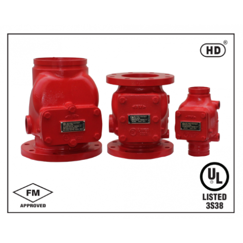
Alarm Valve - HD 247 | Wet Alarm Valve
DESCRIPTION
Alarm Valve is a double seated clapper check valve with grooved seat design, which ensures positive water flow for alarm operation and is designed for installation in wet pipe sprinkler system. External bypass prevents false alarm under all supply pressure
condition. In the event of variable pressure condition, false alarm is prevented with the provision of retard chamber, thus the design allows for installation under both variable and constant supply pressure condition. Operation of one or more automatic fire sprinklers causes the water to flow into the sprinkler system causing the alarm valve to open, allowing continuous flow of water into the system and transmittal of alarm, both electrical and mechanical.
OPERATION
The fire protection system initially when being pressurized, will allow water to flow into the system until water supply and system pressure is equalized and the clapper closes the waterway. Once the pressure is stabilized, the fire protection system is ready to be placed in service and then the alarm control valve must be opened. Under normal condition, the water pressure gauge connected to the system side of the alarm valve would show a higher or equal pressure reading than the water pressure gauge connected to the supply side of the valve. This occurs because of the bypass line connecting downstream and upstream side of the alarm valve, which allows water pressure surge to pass without lifting the valve clapper off its seat, thereby causing excessive high pressure surge entrapped in the system side due to presence of a check valve, which generally prevents false alarm.Sudden high pressure surge, as might be encountered by start-up of a large fire pump may lead the valve clapper to lift momentarily, allowing water to flowthrough grooves in the valve seat to the retard chamber. The water in the alarm line is automatically drained out, which helps to prevent false alarm due to successive transient surge in supply pressure. Restriction assembly located beneath the retard chamber consists of inlet and drain restriction orifices, which are established by considering the volume of the retard chamber to meet the listingand approval requirement with regard to time-to- alarm. These requirements represent a balancing ofthe need to reduce the possible false alarm due to a transient surge in supply pressure and to achieve desired minimum time- to- alarm following a sprinkler operation.
In constant pressure installation, the retard chamber is not required and the water passing through the groove in the alarm valve seat flows directly through restriction nozzle assembly to activate the mechanical and electrical alarm.
INSTALLATION
- HD Sprinkler alarm valve, Model-H must be installed vertically.
- The alarm valve must be installed in a readily visible and accessible location and provision to be made in such a way that alarm line drain is visible and accessible.
- Where water pressure fluctuates, the variable pressure trim with retard chamber must be used. Under non-fluctuating water pressure condition, the constant pressure trim, which does not include retard chamber, may be used.
- The valve must be installed with trim in accordance with the trim data. Failure to follow the appropriate trim connection guidelines may prevent the device from functioning properly as well as void listing, approval and the manufacturer’s warranty.
- Care must be exercised while installing the check valve in the trim to ascertain that they are located with the arrow mark on the check valve body and pointed in proper direction.
- The contraction and expansion associated with an excessive volume of trapped air could cause the waterway clapper to cycle open and shut. This may result in false alarm or an intermittent alarm. To avoid these, it is recommended to have breather valve in the system piping network and a vent valve at the extreme end of the system to bleed-off the air.
- The ball valve provided on the alarm line must be kept open and strapped in set position.
- Pipe connecting the retard chamber and sprinkler alarm bell must be supported
properly to avoid loading on the retard chamber - All the newly installed system pipes must be flushed properly before alarm valve is put into service.
- INSPECTION AND MAINTENANCE
A qualified and trained person must commission the system. After few initial successful tests an authorised person must be trained to perform inspection and testing of the system.
It is recommended to carry out physical inspection of the system at least twice a week. The inspection should verify that all the control valves are in proper position as per the requirement of the system and no damage has taken place to any component. It is recommended that the alarm valve and its
accessories should be examined and performed for following at least quarterly or as demanded by local authorities to ensure reliable and trouble free operation and service.
- Inspection and testing is to be carried out only by an authorized person. DO NOT TURN OFF the water supply valve to undertake repair work or to test the valve, without placing a roving fire patrol in the area covered by the system. The patrol should continue until the system is back into service. Also do inform the local security personnel and alarm control station, so that a false alarm is not signaled.
- Open the alarm test valve. Verify that the sprinkler alarm bell and/or the pressure alarm switch electric alarm properly actuate. Close the alarm test valve and verify that water has ceased to flow from the alarm line drain.
- Clean the 20 NB (3/4”) strainer provided on the sprinkler alarm bell line.
- Clean the strainer of restriction assembly.
- Inspect the check valve clapper located on the bypass line.
- WEIGHT IN KG
| Valve Size | Flange X Flange | Flange X Groove | Groove X Groove |
| 200 | 65 | 54.0 | 44.0 |
| 150 | 42 | 35.8 | 28.0 |
| 100 | 27 | 22.1 | 17.30 |
| 80 | 18 | 15.0 | 12.10 |
- GROOVE PIPE SIZE
| NORMAL SIZE | Pipe OD in MM |
| 3” (80 NB | 89 |
| 4” (100 NB) | 114.3 |
| 6” (150 NB) | 165.1 |
| 6” (150 NB) | 168.3 |
| 8” (200 NB) | 219.1 |
| Returns Policy: |
| 1. | Once orders are placed, cancellations are not permitted. |
| 2. | Payments for orders will not be adjusted or refunded in case of cancellation. |
| Shipping & Delivery Policy: |
| 1. | 100 INR will be charged as shipping fee if buyer and seller are from same city. If Buyer and Seller are from different cities, the shipping charges will be on "To Pay Basis" or at actuals. |
| 2. | Shipping freight costs will be additional and based on actuals, to be borne by the buyer. |
| 3. | Additional shipping services such as courier or door delivery will incur extra charges, to be borne by buyer on extra at actuals basis |
| 4. | Material will be shipped exclusively on a To-Pay basis for Godown Delivery only. |