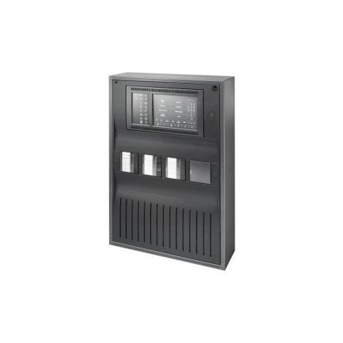
Addressable Fire Alarm Panel | AVENAR panel 2000 | BOSCH

| Product Name | Addressable Fire Alarm Panel | AVENAR panel 2000 | BOSCH |
|---|---|
| Weight | 1.000000 |
| COUNTRY OF MANUFACTURE | India |
| Brand | Bosch |
| HSN Code | 85319000 |
| System Type | CONVENTIONAL |
| Model | FPA-2000-PWM |
| Freight | To pay by Customer, extra at actuals. Godown Delivery |
| Category | Alarm System, Addressable System, Fire Safety |
| Product Code | CPK-0018 |
• Compact modular fire panel, expandable up to 4 loops, provides customized solutions for small to medium size applications
• High resolution display with bright colors to indicate alarms and events
• 8" touch pad with fixed and programmable buttons, thus adaptable to the situation
• Integrated Ethernet switch for networking and interfaces to remote services, building management and voice alarm systems
• Adaptable to local requirements and regulations
The fire panel allows mixed operation of analog addressable and conventional technology. It supports
connecting periphery in either stub or loop topologies. Analog addressable fire detectors, manual call points, signaling devices, inputs and outputs are identified and managed by the fire panel as single elements. As required by the building structure the peripherals are grouped software wise in logical zones. The compact modular fire panel comes as a kit in a housing. The functional modules can be plugged onto the rail inside the housing. The rail provides power and internal communication to the functional modules.
A wide range of functional modules is available providing different connections and functions: addressable loops, conventional zones, inputs and outputs as well as interfaces to various devices. The fire alarm panel can be equipped with six functional modules of which a maximum of four can be analog addressable loop modules. This makes the fire panel suitable for small to medium size applications. The fire panel is available with two different types of housings:
• Wall mount housing
• Frame mount housing
The slim wall mount housings are for mounting directly to the wall. Frame mount housings require an additional frame between the housing and the wall.
The frame lets space for e.g. cabling, media converters, and larger batteries. Special installation
kits also allow installation in 19" racks. The panel controller is the central component of the fire panel. A color display shows all messages. The touch screen is for operation of the entire system. The user-friendly interface adapts to various situations. This causes correct operation that is simple and clear as well as targeted and intuitive. Panels and keypads of the AVENAR series and of the
FPA-5000 series (MPC-xxxx-B and MPC-xxxx-C) can be combined in one panel network using the Ethernet and the CAN bus interfaces. The remote keypad is for decentralized operation of the panel or of the panel network. Integration into large-scale systems can be done by an Ethernet interface to the Bosch Hierarchy panel (UGM) or to Building Integration System (BIS). Integration into third party management systems is possible with the availability of OPC server and
Software Development Kit. A data interface enables monitoring and full control of Bosch voice alarm systems. This makes the fire panel a complete safety solution. The fire panel is configured on a laptop using the FSP-5000-RPS programming software. The programming software enables further adaptation, e.g. to country-specific requirements and regulations.
1 FPE-2000-PPC Panel controller, premium license
2 BCM‑0000‑B Battery Controller Module
3 LSN 0300 A LSN bus module 4 PRS-0002-C Panel Rail Short
5 PRD 0004 A Panel Rail Long 6 Power supply bracket
7 Power supply unit 8 CPH 0006 Panel Housing for
6 Modules
9 Batteries
Functions
AVENAR panel 2000 is a compact modular fire panel for small to medium size systems. It comes standard in a housing with panel controller, power supply, battery controller module and one LSN loop module. Depending on the project specific needs, the fire panel can be extended with up to four LSN 0300 A loop modules, in total six functional modules. Each loop can contain up to 254 LSN elements.
Alarm indication
All messages are shown on the display with a bright color. The displayed messages contain the following
information:
• Message type
• Type of the triggering element
• Description of the exact location of the triggering element
• Logical zone and sub-address of the triggering element
18 Icon LEDs give continuous information about the operating status of the panel or the system. A red icon LED shows an alarm. A blinking yellow icon LED shows a fault. A steady yellow icon LED shows a disabled function. A green icon LED shows proper
operation. Two status LEDs, one red and one yellow, are programmable. The red one shows a self-defined alarm. The yellow one shows a self-defined fault or deactivation. Additional annunciator modules, each with 16 red and 16 yellow LEDs are available to indicate a larger number of self-defined alarms, faults or deactivations.
Operation and processing of messages
For operating the panel, an 8 inch touch pad as input medium is put upon the display. There are 6 buttons with fixed functionality as well as 3 programmable function keys.
Examples for the assignment of the function keys:
• Set the panel controller to day mode, set the panel controller to night mode
• Enable detection points or outputs, disabledetection points or outputs
• Set standard sensor sensitivity, set alternative sensor sensitivity
Each function key has a virtual status indicator. At any time, an operator with sufficient user rights can control the function keys.
Overview of evacuation zones and outputs
At any time, the operator can get a clear overview of each evacuation zone and of each output connected to the fire protection equipment. Each zone and each output is marked with a programmable text label and a clearly distinctive color reflecting the state: Green shows idle state, power is available. Red shows an activation during fire alarm condition, and fuchsia an activation without a fire alarm condition. Yellow shows a fault or disabled state. An operator with sufficient
user rights is able to start the evacuation in selected zones and activate outputs connected to the fire protection equipment through the user interface.
Smart Safety Link
Smart Safety Link is the most reliable and secure interface to combine a fire detection and a voice alarm system (VAS). Smart Safety Link offers exceptional flexibility and options for expandability.
The bi-directional data communication establishes a supervised connection between the fire detection panel and the VAS. Both the fire panel and the VAS indicate a fault message when the connection is interrupted. In case of an interrupted connection, the user can start the evacuation of the complete building manually by using a call station of the VAS. An interruption of the interface does not lead to an automatic evacuation of the building. When the interface is re-established, the fire panel automatically re-synchronizes the current alarm state with the VAS. In case of a fire condition, the fire panel can
automatically start voice announcements using virtual VAS triggers that are activated by rules which are configured in FSP-5000-RPS. The fire panel generates a supervisory message when an evacuation event is started from the VAS. A malfunction on the VAS will generate a fault message on the user interface of the fire panel.
Saving and printing messages
The history log keeps incoming alarms and events internally. The history log has a capacity to store
10000 messages. The messages can be shown on the display, and you can export the messages.
Additionally, you can connect a log printer via a serial interface module for real-time printing incoming messages.
Languages
The operator can change the language of the user interface. A quick user guide for each language is
available. Following languages are included in the package: English, German, Bulgarian, Croatian, Czech, Danish, Dutch, Estonian, French, Greek, Hungarian,Italian, Latvian, Lithuanian, Polish, Portuguese, Romanian, Russian, Serbian, Slovak, Slovenian, Spanish, Swedish and Turkish.
The quick user guides of following languages are available only online at www.boschsecurity.com:
Hebrew and Ukrainian.
Operator management
The system can have up to 200 different registered operators. Login is permitted with a user ID and an 8- digit pin code. There are four different authorization levels. Depending on the authorization level it is possible for the operator to do certain functions according to EN54-2.
Licenses
The panel controller is delivered with a hard coded software license. This software license is implemented during production and cannot be modified, revoked or transported. The license defines the maximum panel network size and availability of certain features and interfaces.
| Ethernet interface to | ||
| Building management system (OPC server, BIS, FSM-5000-FSI) | ||
| UGM-2040 Hierarchy panel | ||
| Voice alarm system (Smart Safety Link) | ||
| Monitoring and control | ||
| Status overview | ||
| Simultaneous control | ||
| Individual control | ||
| Modularity (maximum number) | ||
| Slots for functional modules (max number including slots for LSN modules) | 6 | 6 |
| LSN modules (max number) | ||
| LSN 0300 A modules (1 slot per module) | 4 | 4 |
| LSN 1500 A modules | 0 | 0 |
| Panel redundancy | ||
| Redundant panel controller | ||
| Keypad as redundant panel controller | ||
| Network | ||
| Panel network | remote keypads | panels, remote keypads, servers |
| Max. number of nodes | 4 (1 panel, 3 keypads) | 32 |
In total four AVENAR panel 2000 kits are available:
• FPA-2000-SFM: Standard license. Frame mount housing
• FPA-2000-PFM: Premium license. Frame mount housing
• FPA-2000-SWM: Standard license. Wall mount housing
• FPA-2000-PWM: Premium license. Wall mount housing
| CTN | Description | FPA-2000-SFM | FPA-2000-PFM | FPA-2000-SWM | FPA-2000-PWM |
| FPE-2000-SPC | Panel controller, standard license | 1 | - | 1 | - |
| FPE-2000-PPC | Panel controller, premium license | - | 1 | - | 1 |
| CPH 0006 A | Panel Housing for 6 Modules | 1 | - | ||
| FBH 0000 A | Mounting frame, large | 1 | - | ||
| HCP 0006 A | Panel Housing for 6 Modules | - | 1 | ||
| FPO-5000-PSB-CH | Power supply bracket | - | 1 | ||
| LSN 0300 A | LSN bus module 300mA | 1 | |||
| BCM-0000-B | Battery Controller Module | 1 | |||
| PRS-0002-C | Panel Rail Short | 1 | |||
| PRD 0004 A | Panel Rail Long | 1 | |||
| UPS 2416 A | Universal Power Supply | 1 | |||
| FDP 0001 A | Dummy Cover Plate | 3 |
Functional modules
Functional modules are independent encapsulated units. They are placed into a slot of a panel rail. The power supply and the data traffic with the panel are therefore provided automatically. The module is identified by the panel with no further settings and operates in the default operating mode (plug and play).
Wiring to external components is performed using compact connector/screw terminals. After a replacement, only the connectors need to be reinserted, there is no need for extensive rewiring.
| Module | Description | Function |
| ANI 0016 A | Annunciator module | Indicating system statuses, with 16 red and 16 yellow freely programmable LEDs |
| BCM-0000-B | Battery controller module | Controlling the power supply to the panel and the battery charge level |
| CZM 0004A | Conventional zone module | Connecting conventional peripheral devices using four monitored conventional lines |
| ENO 0000B | External notification module | Connecting fire service equipment complying with DIN 14675 |
| FPE-5000-UGM | Module interface to UGM | Connection to UGM systems |
| IOP 0008 A | Input-output module | Individual displays or flexible connection of various electrical devices, with 8 independent digital inputs and 8 open collector outputs |
| IOS 0020 A | Communication module, 20mA | With S20 and RS232 interfaces |
| IOS 0232 A | Communication module, RS232 | Connection of two devices using two independent serial interfaces, e.g. Plena or a printer |
| LSN 0300 A | LSN bus module 300mA | Connection of an LSN loop with up to 254 LSN improved elements or 127 LSN classic elements at a maximum line current of 300 mA |
| NZM 0002 A | Notification appliance zone module | Allows connection of two conventional, monitored notification appliance circuit lines |
| RMH 0002 A | Relay module high-voltage | Monitored connection of external elements with feedback, with two changeover contact relays suitable for switching mains voltage |
| RML 0008 A | Relay module low-voltage | For low voltage switching, with eight changeover contact relays |
Notice
Safety Systems Designer can be used to plan fire alarm systems that conform to the relevant limits (e.g. in terms of cable length and power supply).
Notice
Safety Systems Designer for fire alarm systems enables the system dimensions, the energy requirements and the quantity and prices of the elements required to be estimated at each
different phase in the planning process.The software is designed for planners and engineering offices that want to produce a quotation for a fire alarm system.
Detection points
Each element or input that can trigger an alarm counts as an detection point. In accordance with EN54-2, do not connect more than 512 detection points and manual call points to one AVENAR panel 2000! In case of more than 512 detectors and manual call points, apply the detectors to more AVENAR panels. All elements and inputs that do not use the Input type in the Message type setting are regarded as detection points. Therefore, all elements and inputs for which
one of the following settings is programmed as the Message type are regarded as detection points:
• Fire
• Internal fire
• Supervisory
• Multi-criterion
• Smoke
• Fault
• Heat
• Water
Only some of these message types are available for selection depending on the element type. The
elements and inputs that can trigger an alarm include all manual and automatic detectors, as well as the modules and interface modules listed below on the basis of the available inputs.
| Modules | Detection Points |
| CZM 0004 A | Up to 4 (1 detection point per zone) |
| IOP 0008 A | Up to 8 (1 detection point per monitored input) |
| RMH 0002 A | Up to 2 |
| ENO 0000 B | requires 1 detection point only if a FSE release element is connected and programmed using the FSP-5000-RPS programming software |
| FPP‑5000‑TI | 2 |
| Interface Modules | Detection Points |
| FLM-420/4CON | Up to 2 |
| FLM-420-I8R1 | Up to 8 |
| FLM-420-I2 | Up to 2 |
| FLM-420-O8I2 | Up to 2 |
| FLM-420-O1I1 | Up to 1 |
| FLM-420-RHV | Up to 2 |
| FLM-420-RLE-S | Up to 2 |
Networking
A panel controller with premium license can be networked with up to 32 panel controllers, remote
keypads and OPC servers. Panels and keypads display all messages, or you can form a group of panels and keypads. Within one group, only messages of this group are displayed. A variety of fire alarm network topologies are possible:
• CAN loop
• Ethernet loop
• Ethernet/CAN double loop
• CAN loop with Ethernet segments
• Ethernet backbone with sub-loops (Ethernet/CAN)
Interfaces
The panel controller features
• 2 CAN interfaces (CAN1/CAN2) for networking
• 1 Rail connector
• 4 Ethernet interfaces (1 / 2 / 3 / 4) for networking,
prescribed usage:
– 1 and 2 (blue): Panel network
– 3 (green): Building management system,
hierarchy panel, voice alarm system
– 4 (red): Remote Services
• 2 signal inputs (IN1/IN2)
Fire Alarm Systems - AVENAR panel 2000
• 1 USB function interface for configuration via FSP-5000-RPS
• 1 Memory card interface
Regulatory information
| Region | Regulatory compliance/quality marks | |
| Germany | VdS-S | S 221001 VdS-S_S221001_AVENAR series |
| Europe | CPR | 0786-CPR-21700 AVENAR panel 2000 |
| Morocco | CMIM | AVENAR panel 2000 |
| Malaysia | BOMBA | 23-341 AVENAR panel 2000 | AVENAR keypad 8000 |
| Israel | SII | 7152327292 AVENAR panel 2000 |
| Serbia | KVALITET | AVENAR panel 2000 |
| Slovakia | PHZ | 2021002517-2 AVENAR panel 8000 | AVENAR panel 2000 | AVENAR keypad 8000 |
| Ukraine | DCS | 0000963-20 AVENAR panel 2000 |
| United Arab Emirates | MOI | 2013-3-56006 AVENAR panel 8000 | AVENAR panal 2000 |
| Macao Special Administrative Region Government | CB | 2069/GEL/DPI/2023 |
| Germany | VdS | G 220048 AVENAR panel 2000 |
| Switzerland | VKF | AEAI 31626 AVENAR panel 8000 | AVENAR panel 2000 | AVENAR keypad 8000 |
| Europe | CE | AVENAR panel 2000 |
| Belgium | BOSEC | B - 9174 - FD - 894 |
| Poland | CNBOP | 4289/2021 AVENAR panel 2000 |
| Sweden | SBSC | 20-486 FPA-2000 |
| Czech Republic | TZÚS | 080-023743 AVENAR panel 8000 | AVENAR panel 2000 | AVENAR keypad 8000 |
Installation/configuration notes
The FSP-5000-RPS programming software enables adaption to project- and country-specific
requirements. The programming software and the associated documentation can be found at
www.boschsecurity.com for those with accessrights.
Information about the programming software is also included in FSP-5000-RPS online help.
General planning instructions
• Country-specific standards and guidelines must be considered during planning.
• The regulations issued by regional authorities and institutions (e.g. fire service) must be adhered to.
• Please note that standards and guidelines may require that a maximum of one function in more than one zone may fail.
For example, if the auxiliary power fails, only the fire detectors and/or manual call points of one zone
may fail.
• We recommend the use of loops wherever possible, as they offer far greater security than stub lines.
• Terminating each stub and each T-tap with EOL modules is essential to set up a complete fire alarm
system with extended line monitoring (creeping short circuit and creeping open monitoring).
• Conventional detectors of the Bosch portfolio for fire products can be connected using one of the
following methods:
– Using the CZM 0004 A 4 Zone Conventional Module The module provides four DC primary lines
(zones).
– Using an FLM-420/4‑CON GLT interface module on the LSN bus for two zones
• Consider the system limit for the number of LSN
elements.
• Each element and input which is able to set off an alarm requires a detection point. Inputs are
considered as detection points if they are programmed accordingly using the FSP-5000-RPS Programming Software.
• In accordance with EN 54-2, no more than 512 detectors and their functions may fail if a system
component fails.
• 12 V/45 Ah batteries can only be used with the frame installation housings.
• Use fuses complying with national regulations to protect the power lines.
• Recommended fire detector cable: J-Y(St)Y 2 x 2 x 0,8 mm, red.
System limits for each LSN module
• It is possible to combine LSN interface modules, LSN detectors and notification appliances on one
loop or stub line.
• For a mixed connection of LSN classic elements and LSN improved elements, a maximum of 127 elements are permitted.
• The use of unshielded cables is possible.
• Limits per LSN 0300 module:
– Up to 127 LSN classic elements or 254 LSN improved elements can be connected
– Current consumption of up to 300 mA
– Cable length of up to 1600 m
Environmental Conditions
• Assembly and operation of the fire panel must be carried out in a clean and dry indoor location.
• Permissible relative humidity: max. 95 % at 25°C,
non-condensing
• To ensure optimum battery service life, the panel should only be operated at sites with normal room temperatures.
• Do not operate devices showing condensation.
Positioning
• Operating and display elements should be positioned at eye level.
The distance between the upper edge of the housing and the center of the panel controller display is around 11 cm. For example, if the eye level required is 164 cm, the housing upper edge installation dimension is 175 cm.
• For frame installation housings, a clearance of at least 230 mm is required to the right of the last
housing to swivel out the installed housing (e.g. for connection, maintenance or service).
• Sufficient space should be left below and next to the panel for any possible extensions, e.g. for an additional power supply or an extension housing.
Building Management System
• If connected to a building management system (Bosch Building Integration System BIS) via an
Ethernet interface using an OPC server, the following must be noted:
In a multi-building network, it is essential to clarify with the network administrator whether the
network is designed for multi-building connections (e.g. no interference due to differences in grounding potential).
Panel Controller Firmware
Two firmware versions are available for the panel controller of the fire panel: version 3.x and version
4.x. Firmware V3.x enables networking compatibility with the legacy FPA-5000 series panels (MPC-xxxx-B and MPC-xxxx-C) and the FMR-5000 keypad. This implies that when AVENAR panel and AVENAR keypad are running firmware V3.x, they only contain bound product features and peripherals that are also available for the FPA-5000 series. From January 1, 2022 to December 31, 2025, panel firmware version 3.x is in maintenance mode. During this period, new versions will be released only containing fixes for critical bugs and critical security gaps.
From January 1, 2022 onwards, new product features, new LSN peripherals, new GUI languages, and normative changes will be only available in firmware version 4.x. Firmware version 4.x is exclusively for AVENAR panel and AVENAR keypad.
Technical specifications
General system limits
| Panels/remote keypads/OPC servers in the network | Max. number |
| Ethernet / CAN (premium license) | 32 |
| LSN elements | Max. number |
| Stand-alone pane | 1016 |
| Per network panel | 1016 |
| Total network | 32512 |
| Detection points | Max. number |
| EN 54 compliant panel | 512 |
| Stand-alone panel, not EN54 compliant | 4096 |
| Networked panel, not EN 54 compliant | 2048 |
| Total network | 32768 |
| NAC groups | Max. number |
| NAC groups with more than one FNM-420, per loop | 6 |
| Voice alarm system | Max. number |
| In CAN network, per panel (premium license) | 1 |
| In total Ethernet network (premium license) | 1 |
| Triggers (each trigger counts as one sounder group) Ethernet interface | 244 |
| Triggers (each trigger counts as one sounder group) RS-232 interface | 120 |
System limits per fire panel
| Per fire panel | Max. number |
| Sets, e.g. bypass group These sets include sets which are automatically created for each LSN bus. | 192 |
| Per fire panel | Max. number |
| Functional modules | 6 |
| Printer | 4 |
| Alarm counters (external, internal, testing) | 3 |
| Entries in the event database | 10000 |
| FSP-5000-RPS configuration interfaces (USB) | 1 |
| Maximum number of outputs (sounders, controls, etc.) activated in parallel due to the same event | 508 |
Configuration limits per fire panel
| Configuration limits per fire panel (FSP-5000-RPS) | Max. number |
| Timer channels | 20 |
| Time control programs | 19 |
| Configuration for a Specific Day | 365 |
| Permission levels | 4 |
| User profiles | 200 |
| Sum counters and counters (in total) | 60000 |
| Exportable objects including counters in the entire panel cluster (without pre-defined system counters) |
2000 |
| Importable objects including counters (without predefined system counters) | 2000 |
| Automatic connections to remote keypad | 3 |
| Blocks of State-Dependent Rules (depending on what kind of activations are possible) |
8 |
| Maximum number of rules within a block | 254 |
Number of functional modules
| Functional modules | Max. number |
| ANI 0016 A | 4 |
| BCM-0000-B | 5 |
| CZM 0004 A | 4 |
| ENO 0000 B | 4 |
| FPE-5000-UGM | 4 |
| IOP 0008 A | 4 |
| IOS 0020 A | 4 |
| IOS 0232 A | 4 |
| LSN 0300 A | 4 |
| LSN 1500 A | 0 |
| NZM 0002 A | 4 |
| RMH 0002 A | 4 |
| RML 0008 A | 4 |
Power loss of panel components
| Component | Power loss |
| ANI 0016 A | 0.62 W (all LEDs lit) |
| BCM‑0000‑B | • 0.96 W (controller + green LED lit) • 1.44 W (per AUX with 1.06 A load) |
| CZM 0004 A | • 1.65 W (for a line with 100 mA load) • 3.36 W (for 4 lines with 100 mA load each) |
| ENO 0000 B |
• 1.44 W (1 relay activated) • 7.80 W (4 relays activated + key |
| FPE-2000-PPC | max. 11 W |
| FPE-2000-SPC | max. 11 W |
| FPE-5000-UGM | 0.17 W |
| IOP 0008 A | 0.24 W |
| IOS 0020 A | 0.36 W |
| IOS 0232 A | 0.36 W |
| LSN 0300 A | • 1.50 W (AUX with 490 mA load) • 2.72 W (LSN) |
| NZM 0002 A | 0.96 W |
| PRD 0004 A | 0.07 W |
| PRS-0002-C | 0.07 W |
| RMH 0002 A | 1.16 W |
| RML 0008 A | 1.04 W (all relays activated) |
| UPS 2416 A | 28.00 W |
Electrical
| Input voltage range | 100 - 240 V AC |
| Input frequency range | 50 Hz to 60 Hz |
| Power source (EN 62368-1) | PS 3 |
| Electrical source (EN 62368-1) | ES 3 |
| Terminals 24 V+/- ①, 24 V+/- ②: | |
| Output voltage (min-max) | 20.4 - 30 V battery-buffered |
| Output current (min-max) (x 2) | 0 - 2.8 A |
| Power source (EN 62368-1) | PS 2 |
| Electrical source (EN 62368-1) | ES 1 |
Mechanical
| Dimension wall mount version (H x W x D) (mm) | 638 mm x 440 mm x 149 mm |
| Dimension frame mount version (H x W x D) (mm) | 638 mm x 450 mm x 232 mm |
| Flammability rating | UL94-V0 |
| LCD display (pixels) | 7" color WVGA 800 x 480 |
| Operating and display elements | • 6 keys • 18 LEDs |
| Housing material | Sheet steel, painted |
| Housing color | Slate gray, RAL 7015 |
| Front color | Anthracite, RAL 7016 |
| Battery type for wall-mount version 1 | 12V 24-27Ah |
| Battery type for frame-mount version 2 | 12V 38-45Ah |
1
Order info: IPS-BAT12V-27AH, F.01U.579.781
2
Order info: IPS-BAT12V-45AH, F.01U.579.782
Environmental
| Safety class according to EN 62368-1 | Class 1 equipment |
| Permissible ambient temperature during operation | -5 °C to 50 °C |
| Permissible storage temperature | -20 °C to 60 °C |
| Relative humidity | Max. 95% non-condensing @25 °C |
| Protection category | IP 30 |
| Cooling | Natural convection* |
Ordering information
FPA-2000-SFM Panel kit standard license, frame-mount
AVENAR panel 2000 is a compact modular fire panel for small to medium size systems. It comes standard in a housing with panel controller, power supply, battery controller module and one LSN loop module. Depending on the project specific needs, the fire panel can be extended with up to four LSN 0300 A loop modules, in total six functional modules. Each loop can contain up to 254 LSN elements. The frame-mount panel kit includes a panel controller standard license. Order number FPA-2000-SFM | F.01U.383.887
FPA-2000-PFM Panel kit premium license, frame-mount
AVENAR panel 2000 is a compact modular fire panel for small to medium size systems. It comes standard in a housing with panel controller, power supply, battery controller module and one LSN loop module. Depending on the project specific needs, the fire panel can be extended with up to four LSN 0300 A loop modules, in total six functional modules. Each loop can contain up to 254 LSN elements. The frame-mount panel kit includes a panel controller premium license. Order number FPA-2000-PFM | F.01U.383.893
FPA-2000-SWM Panel kit standard license, wall-mount
AVENAR panel 2000 is a compact modular fire panel for small to medium size systems. It comes standard in a housing with panel controller, power supply, battery controller module and one LSN loop module. Depending on the project specific needs, the fire panel can be extended with up to four LSN 0300 A loop modules, in total six functional modules. Each loop can contain up to 254 LSN elements. The wall-mount panel kit includes a panel controller standard license. Order number FPA-2000-SWM | F.01U.383.886
FPA-2000-PWM Panel kit premium license, wall-mount
AVENAR panel 2000 is a compact modular fire panel for small to medium size systems. It comes standard in a housing with panel controller, power supply, battery controller module and one LSN loop module. Depending on the project specific needs, the fire panel can be extended with up to four LSN 0300 A loop modules, in total six functional modules. Each loop can contain up to 254 LSN elements. The wall-mount panel kit includes a panel controller premium license. Order number FPA-2000-PWM | F.01U.383.888
| Returns Policy: |
| 1. | Once orders are placed, cancellations are not permitted. |
| 2. | Payments for orders will not be adjusted or refunded in case of cancellation. |
| Shipping & Delivery Policy: |
| 1. | 100 INR will be charged as shipping fee if buyer and seller are from same city. If Buyer and Seller are from different cities, the shipping charges will be on "To Pay Basis" or at actuals. |
| 2. | Shipping freight costs will be additional and based on actuals, to be borne by the buyer. |
| 3. | Additional shipping services such as courier or door delivery will incur extra charges, to be borne by buyer on extra at actuals basis |
| 4. | Material will be shipped exclusively on a To-Pay basis for Godown Delivery only. |